Rosen Sound LLC
Rob’s Strip Board
Couldn't load pickup availability
There’s few things in the world Rob Rosen dislikes more than your average strip board, vero board, or other prototyping boards. The reason is that those products don’t usually allow enough connections per net, require too much kludging, never have enough space for connectors, and because they’re not through hole plated, the connections break off the bottom too easily.
So, Rob made his own strip board design to right the wrongs of strip boards of the past.
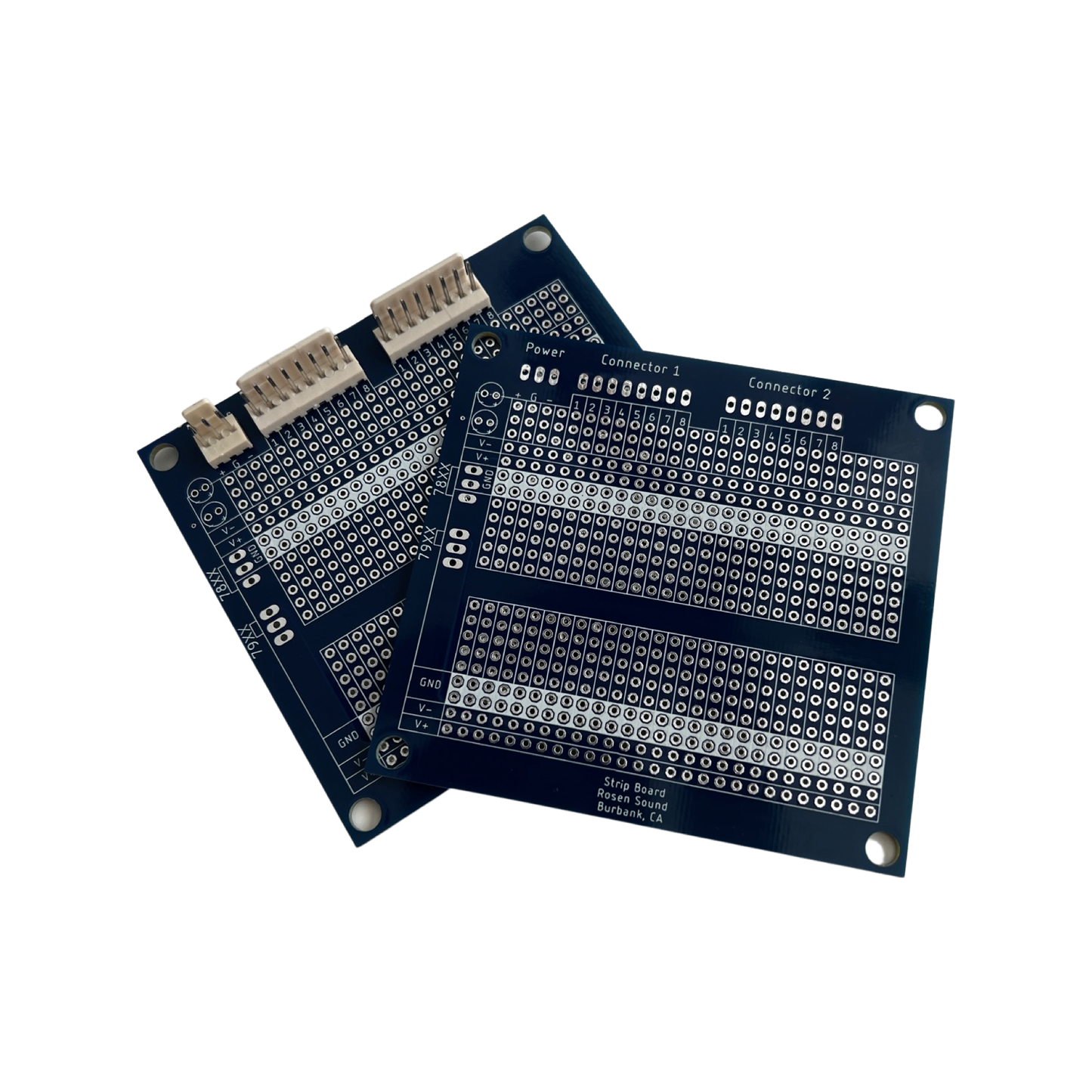
Rob’s strip board is designed to use your average DIP style integrated circuits. Each pin of the IC then has 4 vertical connection points.
On the top of the strip board is space for 3 connectors as described below:
The left most connector is power, with connections for 2 voltages and ground. These are pre routed to 78 and 79 series fixed regulator foot prints as well as bypass capacitor. If on board regulation is not required, simply jump the input to the output as denoted by white lines in the regulator footprint. The output of the regulator is then routed to two horizontal strips of pins of the respective voltage, one one each side of the strip board, making V+ and V- connections easy to access. If regulation is used, be sure to use additional bypass caps as the ones pre-routed are for the input voltage.
The center and right side connectors are free 8 pin connectors to be used as you see fit. Each pin has 3 connection points directly under. While the product photo shows the connector header installed, it is not provided. We will however provide a part number for these connectors.
Ground is easily accessed by 4 horizontal strips with a bright white silk screen, 2 strips on each side of the strip board.
Each “strip” is through hole plated, so damage of the traces or pads is much less likely when the strip board is put into the field. The copper traces are only present on the reverse of the board, making it easier to cut traces if needed.
On the corners of the board are 4 holes with a diameter suitable for 6/32 or M3 hardware.


